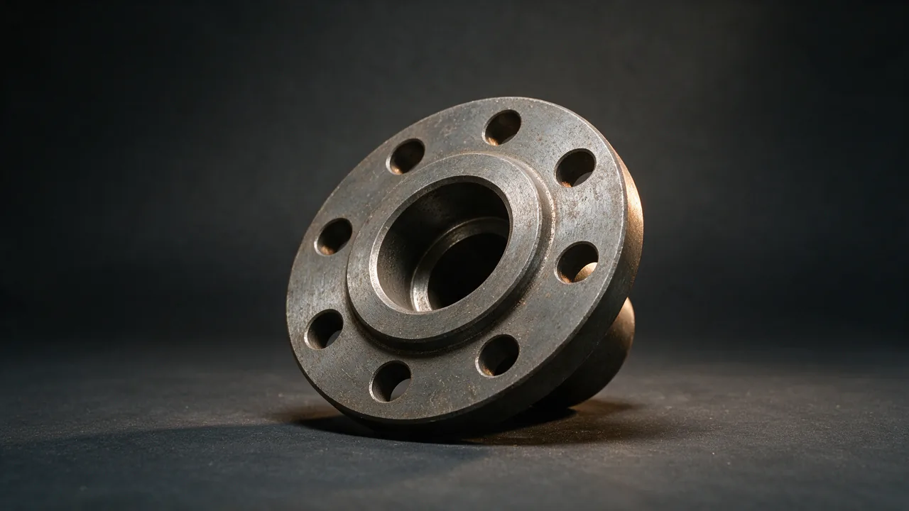
Small bore socket weld flanges to ASME B16.5, forged in carbon, alloy and stainless steel for instrument, utility and small bore high pressure lines.
- Standard: ASME B16.5, ASTM A105, ASTM A182, ASTM A350
- Grades: A105, A350 LF2, F11, F22, F304, F304L, F316, F316L
- Certificate: EN 10204 3.1 with every order, 3.2 on request
Mejor Steel is the export agent for the mills that make your material: one contract, one delivery date, and the mill named on the quotation. How we supply
We reply within one business day, Monday to Friday 09:00-18:00 CST. Or write to info@mejorsteel.com / WhatsApp.
Specifications
| Outer diameter | 1/2" - 4" to ASME B16.5 (highest classes up to 2 1/2") |
|---|---|
| Schedule | Pipe outside diameter and wall only - the pipe fits into the socket bore |
| Length | Flange thickness and socket depth per ASME B16.5 |
| Ends | Raised face (RF), flat face (FF) or ring joint (RTJ) |
| Surface treatment | Black oxide, anti-rust oil, hot dip galvanized, or machined finish |
| Manufacturing process | Forged and machined |
| Pressure rating | Class 150, 300, 600, 900, 1500, 2500 |
| Connection type | Pipe inserted into the socket, single fillet weld outside |
ASME B16.5 Class 150 flange dimensions
Flange outside diameter, minimum flange thickness, bolt circle, bolting and raised face, in millimetres, for NPS 1/2 to 12 in. These dimensions are set by the size and the pressure class and are common to the flange types on this line; the bore, hub, socket or thread detail changes with the type and is confirmed on the drawing or the quotation. Thickness includes the 1.6 mm raised face.
| NPS | DN | Flange OD (mm) | Min. thickness (mm) | Bolt circle / PCD (mm) | Bolts | Bolt size | Hole dia (mm) | Raised face dia (mm) |
|---|---|---|---|---|---|---|---|---|
| 1/2 | 15 | 88.9 | 11.2 | 60.5 | 4 | M14 | 15.9 | 34.9 |
| 3/4 | 20 | 98.6 | 12.7 | 69.9 | 4 | M14 | 15.9 | 42.9 |
| 1 | 25 | 108.0 | 14.3 | 79.4 | 4 | M14 | 15.9 | 50.8 |
| 1-1/4 | 32 | 117.5 | 15.9 | 88.9 | 4 | M14 | 15.9 | 63.5 |
| 1-1/2 | 40 | 127.0 | 17.5 | 98.6 | 4 | M14 | 15.9 | 73.0 |
| 2 | 50 | 152.4 | 19.1 | 120.7 | 4 | M16 | 19.1 | 92.1 |
| 2-1/2 | 65 | 177.8 | 22.4 | 139.7 | 4 | M16 | 19.1 | 104.8 |
| 3 | 80 | 190.5 | 23.9 | 152.4 | 4 | M16 | 19.1 | 127.0 |
| 3-1/2 | 90 | 215.9 | 23.9 | 177.8 | 8 | M16 | 19.1 | 139.7 |
| 4 | 100 | 228.6 | 23.9 | 190.5 | 8 | M16 | 19.1 | 157.2 |
| 5 | 125 | 254.0 | 23.9 | 215.9 | 8 | M20 | 22.2 | 185.7 |
| 6 | 150 | 279.4 | 25.4 | 241.3 | 8 | M20 | 22.2 | 215.9 |
| 8 | 200 | 342.9 | 28.4 | 298.5 | 8 | M20 | 22.2 | 269.9 |
| 10 | 250 | 406.4 | 30.2 | 362.0 | 12 | M24 | 25.4 | 323.9 |
| 12 | 300 | 482.6 | 31.8 | 431.8 | 12 | M24 | 25.4 | 381.0 |
Data to ASME B16.5; confirm against the project specification before fabrication. Sizes above 12 in and Class 300 to 2500 follow the same layout and are quoted against the specification. Send the size, class, facing and destination port and we will confirm availability and price within one business day.
What a Socket Weld Flange Is
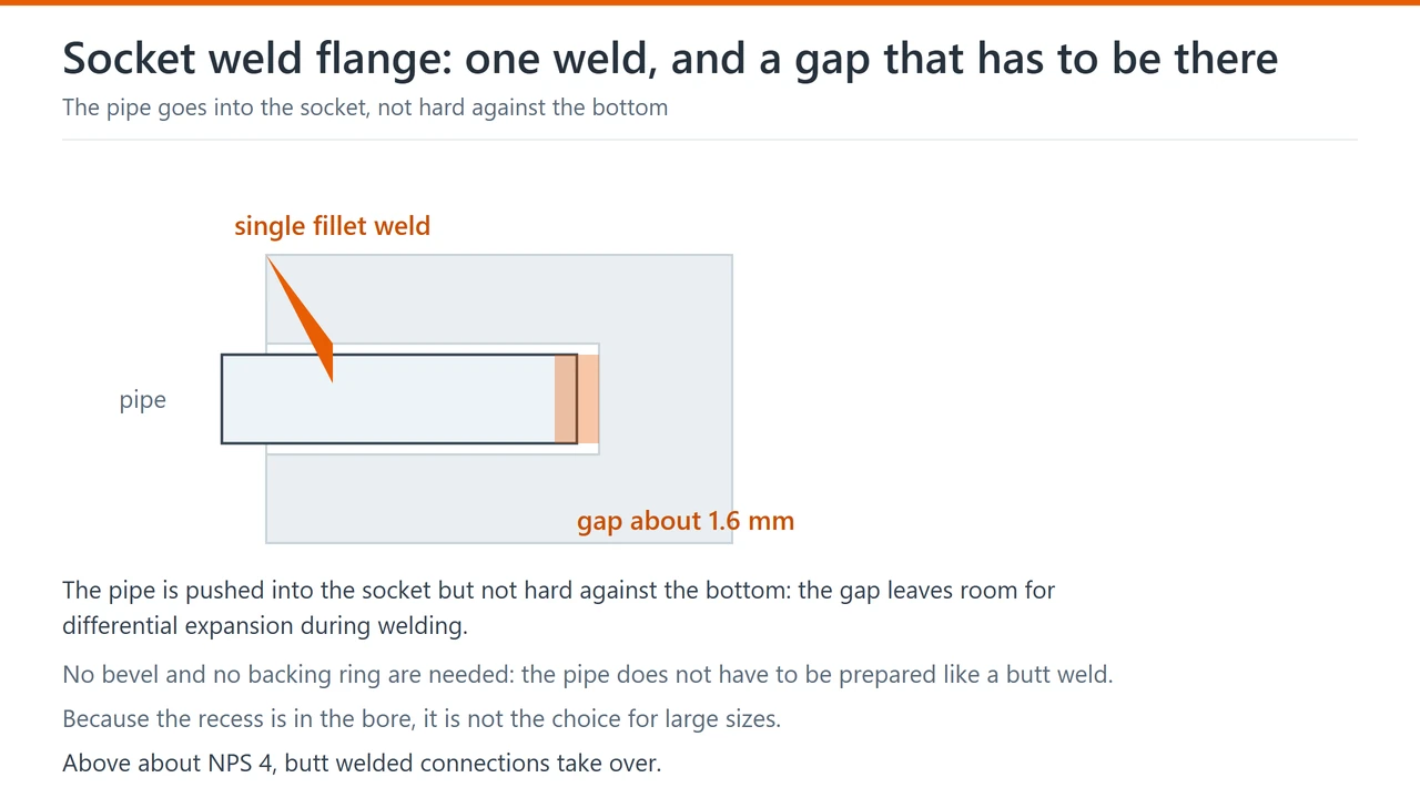
A socket weld flange has a recessed socket in its bore. The pipe end is inserted into the socket and a single fillet weld is run around the outside, so the pipe does not have to be bevelled and no backing ring is needed. Because the pipe sits inside the socket, the two parts are held square to each other while the weld is made, which is exactly what small bore work needs – a small bore butt weld is difficult to fit and to examine.
Size Range and Where It Fits
Socket weld flanges are a small bore product. ASME B16.5 tabulates them up to NPS 4 in the lower classes, and the highest classes stop at NPS 2 1/2, so a socket weld flange cannot be ordered in the larger sizes at all. Typical uses are instrument and impulse lines, small bore drains and vents, chemical injection and sampling points, steam tracing, and small bore connections on high pressure equipment where a welded joint is preferred to a threaded one.
Installation Points That Decide Whether It Leaks
The pipe is pushed into the socket but not hard against the bottom: a gap of about 1.6 mm is left before welding, so that the pipe can expand with the heat of welding without cracking the weld or the flange. Skipping that gap is the most common cause of a cracked socket weld. The single weld is a fillet, so it is examined by dye penetrant or magnetic particle testing rather than radiography. The pipe end must be cut square and deburred, and the socket must be dry and clean before fitting.
Limitations to Know
Because the weld is a fillet, a socket weld joint cannot be radiographed, and it should not be used in severe cyclic service. Fluid can collect in the gap between the pipe end and the bottom of the socket, so socket welds are avoided in highly corrosive or sour service where crevice corrosion is a risk. And because the recess is in the bore, a socket weld connection is not the choice for large sizes – above about NPS 4, butt welded connections take over.
What is the size range of a socket weld flange?
ASME B16.5 tabulates socket weld flanges up to NPS 4, and the highest classes only up to NPS 2 1/2. In practice they are used on small bore lines, roughly NPS 1/2 to 2, and larger lines use butt welded flanges.
Socket weld or threaded flange – which should I choose?
Choose socket weld where a welded joint is acceptable and a leak-tight joint is important, for example on small bore high pressure lines. Choose threaded where welding is not permitted – during tie-ins to a live plant, in classified areas, or where the joint may have to be dismantled. A socket weld joint is stronger and less likely to loosen under vibration; a threaded joint can be taken apart but is more prone to leaking under thermal cycling.
Why is a gap left at the bottom of a socket weld?
The pipe expands when it is heated by welding. If it is already hard against the bottom of the socket there is nowhere for that expansion to go, and the stress can crack the weld or distort the flange. A gap of about 1.6 mm before welding gives the pipe room to move.
Can a socket weld joint be radiographed?
No. The weld is a fillet and radiography cannot resolve it usefully, so the specified examination is dye penetrant or magnetic particle testing. That is one of the reasons a socket weld connection is not used for critical high pressure work where a full volumetric examination is required.
Welding sequence and gap control on a socket weld
A socket weld joint is made in five steps, and the gap sets the other four.
| Step | What is checked | What happens if it is skipped |
|---|---|---|
| Square cut and deburr | Pipe end cut square, burr removed, socket clean and dry | A burr holds the pipe off the bottom, or a burr falls into the socket; both show up as an incomplete weld |
| Mark the insertion depth | The pipe is marked so the insertion depth can be seen after welding | Without a mark there is no way to tell whether the pipe bottomed out |
| Set the gap | A gap of about 1.6 mm is left between the pipe end and the socket bottom | Pipe hard against the bottom has nowhere to expand when it is heated, and the weld or the flange cracks |
| Tack and square | Tack, then check the flange face square to the pipe axis | An out of square flange seats the gasket unevenly |
| Weld and examine | Single fillet weld, then dye penetrant or magnetic particle testing, with the leg size verified against the drawing | Undersized or cracked fillet welds are not visible from the outside and cannot be found by radiography |
What the documents and records should show
- On the flange: the class, size, grade and heat number in the marking, with a mill certificate to EN 10204 3.1, and 3.2 or third party inspection where the project requires it.
- On the weld: the welding procedure reference, the welder identification, the gap actually set, and the result of the dye penetrant or magnetic particle examination.
- On the flange drawing: the inside and outside diameters of the socket matter as much as the face — a socket that is too deep hides the pipe end, and one that is too shallow leaves the weld with nothing to fuse to.
Source: socket weld dimensions and pressure classes from ASME B16.5; the gap, examination method and record requirements are those of the piping code applied to the installation, and should be confirmed against the project specification.
Grades supplied and minimum properties
The grade fixes the minimum strength and the chemistry. The table below gives the requirements that separate the forged flange material grades ordered most often; the full composition and mechanical table for each grade is on its own page.
| Grade | Yield strength | Tensile strength |
|---|---|---|
| A105 (forged carbon steel) | 250 MPa (36,000 psi) | 485 MPa (70,000 psi) |
| F316 (forged stainless steel) | 205 MPa min (30,000 psi) | 515 MPa min (75,000 psi) |
The complete chemistry and mechanical table for each grade, with the notes that qualify it, is on the individual grade page – for example ASTM A105 flange. The stainless grade has the higher tensile requirement but the lower minimum yield strength, so the two are not interchangeable on the strength table alone. The pressure class sets the flange dimensions, so the grade does not set the wall.
Source: specified minimum yield and tensile strength for each grade, per ASTM A105 / ASME SA105 and ASTM A182 / ASME SA182. The standard named against each grade is the governing document.
Download Socket Weld Flange data sheet (PDF) One page: supply range, grades and key sizes, what to state on the enquiry, and the inspection documents that come with the order. The standard is the governing document.
What decides the price
There is no list price for flanges: the same drawing can be quoted at different numbers depending on seven things. Send them and the quotation comes back within one business day.
| Factor | Why it moves the price | What to send |
|---|---|---|
| Material grade | Carbon A105 is the baseline; F316, F51 and alloy grades cost more and take longer to source | The grade, or the line class |
| Size and pressure class | Weight and forging time rise with both | NPS and class |
| Facing | RTJ and special facings add machining | RF, FF or RTJ |
| Bore or schedule | A weld neck is bored to the pipe wall, so the schedule is part of the price | The pipe schedule |
| Quantity | Setup is spread over the pieces; a small lot carries more per piece | Pieces, or total weight |
| Inspection and certificate | EN 10204 3.2 and third-party inspection add cost and time | 3.1 or 3.2, and whether SGS, BV or TUV is required |
| Destination and Incoterm | Freight and packing follow the port | Destination port, FOB / CFR / CIF |
Reply within one business day. Send the seven items above with the quantity and the destination port. Send the specification or WhatsApp the specification.
Materials
- Forged carbon steel
- Forged alloy steel (Cr-Mo)
- Forged stainless steel
Typical applications
- Instrument and impulse lines
- Small bore utility, drain and vent connections
- Chemical injection and sampling points
- Small bore high pressure connections
- Steam tracing and auxiliary lines
Inspection & testing
- Dimensional inspection per ASME B16.5
- Chemical and mechanical testing per ASTM
- PMI on alloy and stainless steel
- Hardness testing
- Dye penetrant or magnetic particle examination of the weld on request
| Packaging | Sea-worthy export packing: wooden cases or pallets, tagged with size, grade and heat number; corrosion protection on request. |
|---|---|
| MOQ | By piece - mixed sizes accepted; no minimum on standard items. |
| Lead time | Stock items: 5-10 days. Made to order: 3-5 weeks after order confirmation. |
Payment: T/T 30% deposit with the balance before shipment; L/C at sight also accepted. Final terms are confirmed on the quotation.
How we supply: sourced through partner mills; the producing mill is named on the quotation. How we supply sets out who is accountable for the order.
Need this product? Send the size, grade, quantity and destination port and we will reply with availability and pricing.
Request a quotation